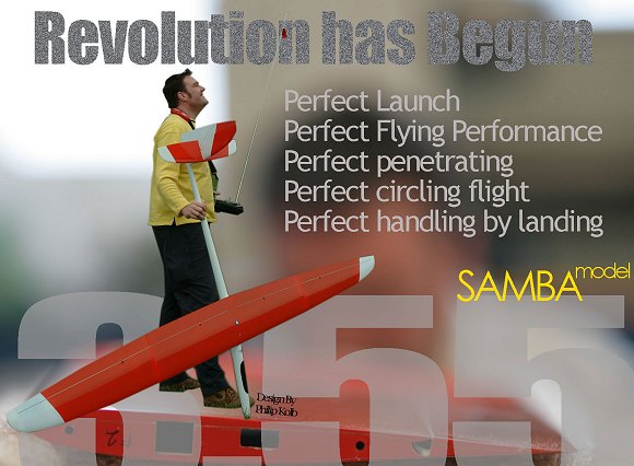
2010 - F5J electro Perfect / Perfect ET
New electric "disser" electric Perfect or
Perfect ET makes incredible light weight electric sailplane.
Read more HERE
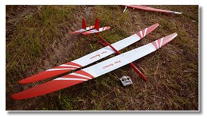
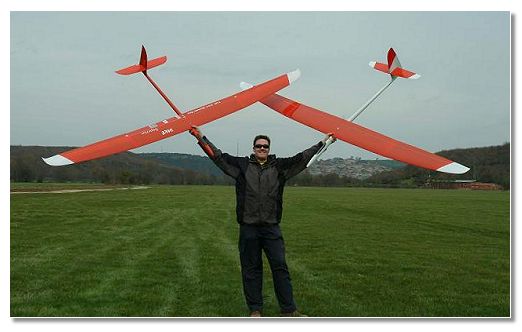
New Pike Perfect ET (Extended Tips) released
Vlastimil flew the new ET tips on Tuesday before the North
Cyprus F3J Open. and in the weekend Jojo won the North Cyprus
F3J Open 2009.
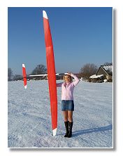
The new tips makes the Pike Perfect 3,78m and is made to improve
circling performance and dead air time. The weekends competition
shows that it is also performing well in both high winds with
ballast and normal conditions.
See some pictures from the first flights
HERE
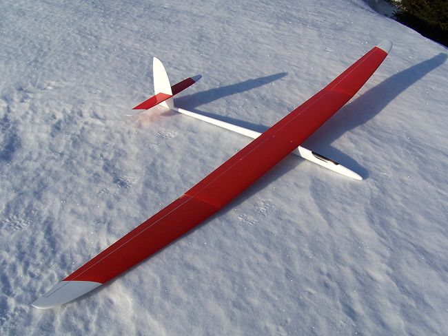
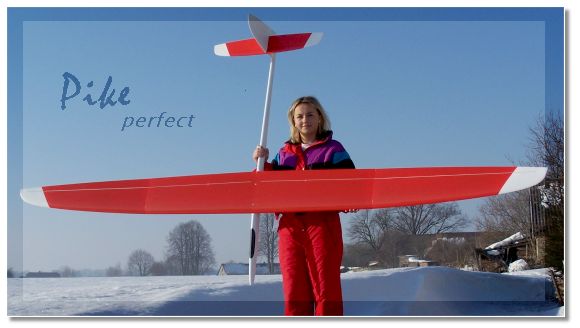
Pike Perfect is in production!
The first models have left the moulds and are now being tested.
This page will progress as we test more and within a week you will see a
complete article explaining how and why things become real.
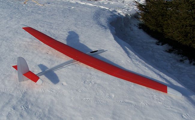
The wing planform for the new all-round F3J-model Pike perfect can be
characterized as follows:
- Large wing area
- Nearly elliptical planform
- Moderate aspect ratio
- Deep chords for high Reynolds numbers
Setup and throws of model will be as usual right here on our page with
detailed settings for both pleasure and competition.
22/10 Larry flew the first 2,4 Perfect
Larry Jolly have flown the first 2,4ghz Pike Perfect.
Read his first thoughts
NEW
15/5 Instructions Perfect
Instructions on building the Pike Perfect is out
Download with pictures (2,2mb .pdf)
or without
pictures
(0,3mb .pdf)
8/4 Perfect start to new model
A Perfect start for our new model. In
the first competition we had 3 Perfect's in the finals and all
places on the podium were Pike's.
Eurotour F3J in Istanbul:
1. Philip Kolb, Pike Perfect
2. Colin Lucas, Pike Superior
3. Jo Grini, Pike Perfect
Some
words from Jojo - Read about Perfect
21/3 More photos by Jojo
Pictures HERE or visit his
diary
19/3 Philip back home
Read more HERE
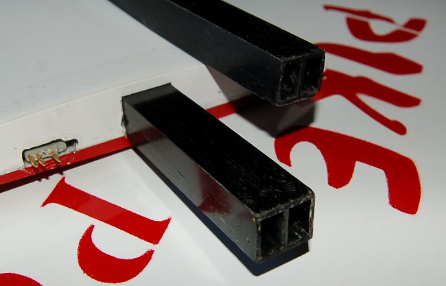
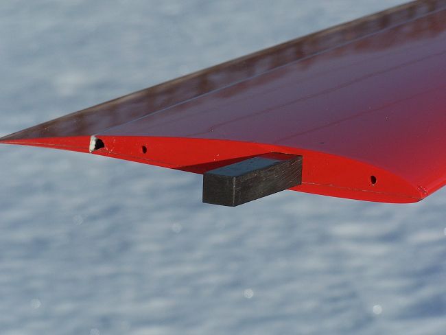
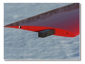
18/3 New joiner
mould ready
The first joiners were solid but we have now made new mould and
saved 17g on each joiner. The new joiners are hollow and weighs 18g
each. That is a total save on 34g. It probably sounds little but
this is out in the tip and makes a difference. We have tested and
they are even stiffer than the first we made!
14/3 Hello out
there!
We are still alive and flying. We spent three more days
experiencing calmer air. Unfortunately it was again far away from
floating conditions.
Read more HERE
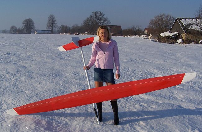
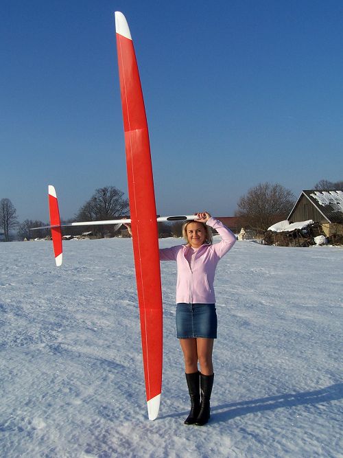
Technical:
Wingspan: 3550mm, Length: 1625mm
Wing area: 74,93dm, Tail area: 7,81dm
Aspect ratio: 16,81
Wing section: PK-91A - PK-91B - PK-92 - PK-93 - PK-94
Tail section: HT-14 - HT-13
Weight: Apx. 2050-2300g depending on lay-up
SL - 68 - 68/80 - 80 - eXtreme
Design by Philip Kolb
|
New Pike Perfect ET (Extended Tips) released
See some pictures from the first flights
HERE

Larry Jolly have flown the first 2,4ghz Pike Perfect.
Read his first thoughts
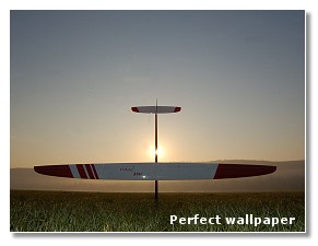
Download wallpaper (click to open and
then right click and "use as background").
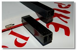
New joiner mould ready
Each joiner is 18g!
And STRONGER than full carbon standard
Read Philip's first days of flying
with Pike Perfect HERE
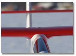
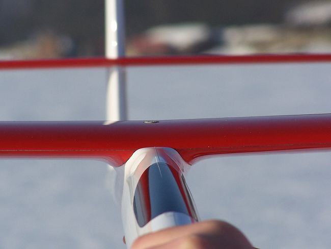
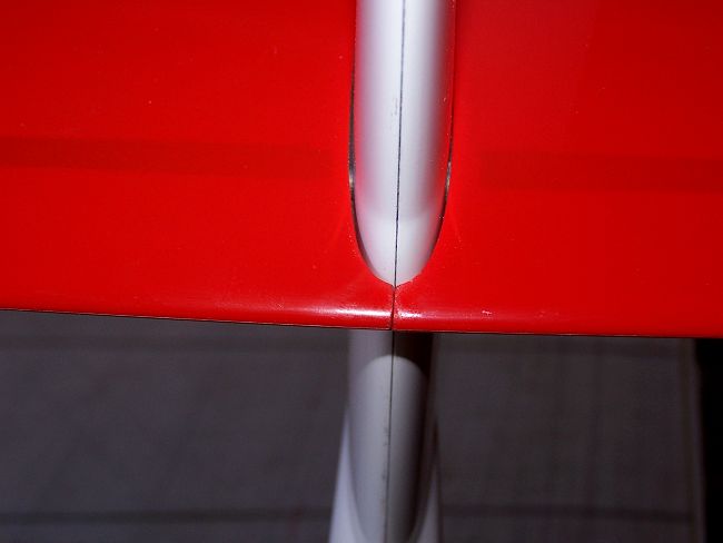
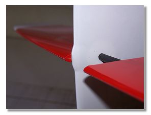
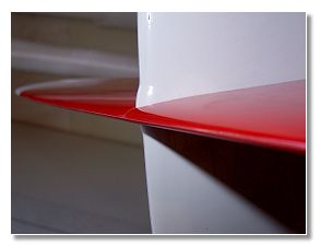
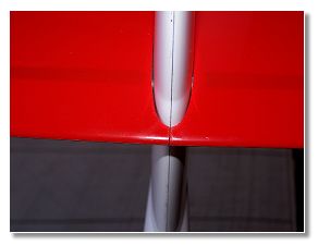
A close up reveals that this is a
Samba model. Everything fits Perfect
and is well thought out. |
Electro fuse |
Tip & tricks | Antenna
solution
| 2,4Ghz installation
|
Setup |
Throws |
Howto |
More photos
|
| Neutral elevator |
Instructions with pictures (2,3mb .pdf)|
Instructions
without pictures (0,3mb .pdf)|
|
Color design |

Pike Perfect
The Quest for the Ultimate F3J-Model
High quality moulded glider designs now dominate the F3J Class. The F3J pilot
has to decide which one of the many excellent models currently available he will
use in competition. The majority of these models offer excellent performance
potential, and are built to the highest standards now expected for competition
F3J models.
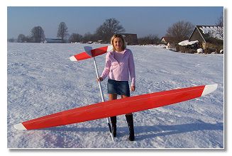
Writer of this article. Philip Kolb with his Pike
Superior and Pike Perfect
So what keeps designers and constructors trying hard to push
the limits and expending their energy on new designs? Is there still potential
performance to be had in the evolution of F3J glider design? Is it worth the
time and effort to design a new glider with so many excellent moulded models
already available?
Considering the gliders flown at the F3J World Championship in 2004 it is
interesting that the majority of pilots have embraced the strategy of utilising
two different designs to cope with various weather conditions. Usually a large
and light glider is used for floating conditions expected in the morning or
evening rounds. However, an agile and stiff model capable of being ballasted is
desirable in “launching and landing” conditions, or where there is windy and
turbulent weather, a heavier and more agile design offers the best potential for
the winning solution.
Pilots choosing one design will find it challenging to adapt to all conditions.
One strategy is to choose a design that handles well in normal conditions and
then carefully lighten the structure to cope with the dead air rounds. This
strategy can prove difficult as the lighter model may not handle as well with
the lighter wing loading, and may prove structurally deficient when the
competitor attempts to add ballast for normal conditions. Very often these
pilots have to admit that there are other models better suited for some
conditions and they find themselves at a disadvantage. A pilot who chooses to
fly the optimal model for the air present in a particular round may be
frustrated by the 3 model rule if he is unlucky enough to damage a given model
and find his other optimised models not suitable for the conditions encountered
in later rounds.
So it is obvious that the real challenge is to design and construct a new model,
which will offer the best performance, over a maximum range of conditions. Some
try to continue the evolution of an existing design, step by step, fixing each
problem as they are encountered. One popular example is to increase the wingspan
and wing area. This method is widely accepted and is helpful, especially when
changes need to be made to optimise a heavy model for lighter conditions.
Performance improvements can be expected up to a certain point, but in the end,
the performance gains will be marginal. These changes can have unexpected
results, sometimes adversely affecting the performance of the original design. A
change in wingspan for example will have effects on the tail moment arm, tail
volume, and lift distribution of the wing. Therefore a complete new design can
offer more favourable results, versus redesigning parts on an existing model.
This is the principal I embraced while designing the Pike Perfect
The new model was designed to be the next step, combining both the floating
abilities of the large and light F3J gliders, and the manoeuvrability and
launching capabilities of the smaller ones. It is designed with the expectation
that no sacrifices have been to the handling qualities of the model. Experience
shows that this point is paramount; especially in difficult conditions, when
handling qualities prove more important than theoretical performance. These
thoughts have led to the design and development of Pike Perfect shown in the
following lines and figures.
The geometric design of the wing:
Designing the optimal wing planform, lift distribution, aspect ratio, and the
local Reynolds numbers were considered paramount for achieving the desired
performance. All of these parameters affect each other, and the designer must
make concessions so that the performance goals are achieved. The lift
distribution was the first parameter defined because of its fundamental effect
on performance.
The circulation is proportional to the local lift at the local chord. As a
result the maximum circulation will be at the root chord of the wing, where the
lift and chord are maximum. To minimize the induced drag of the wing, the
circulation has to decrease elliptically along the span, towards the tip of the
wing. Building an elliptical tapered wing offers the advantage of a relatively
low tip volume and thereby lighter weighted tips, which helps to keep the plane
agile. Conversely, Reynolds numbers will get very low with narrow tips, which
increases the airfoil drag, and even worse, will have effects on the stall
characteristics of the plane, thereby inducing tip stall problems if the tips
are too narrow. The cl_max at the tip is reached earlier than the cl_max at the
root. In this case the choice will be a slightly over elliptical planform. The
25% chord line is kept straight in the centre of the wing to keep the torsion
forces as low as possible and is swept back at the tip. The hinge lines (75%
chord) of the flaps and the ailerons are straight to have identical depth of
flaps all over the wing.
The next parameter of interest is the aspect ratio. An F3J model will primarily
fly at relatively high lift coefficients, as compared to a speed model. The
proportion of the induced drag to the entire drag will increase with the lift
coefficient, so trying to reduce the induced drag is the way to go. Utilizing an
elliptical planform is a good start, but greater performance gains can be
expected by increasing the aspect ratio. Increasing the aspect ratio to reduce
the induced drag can be achieved by increasing the wingspan or reducing the
chord depths of the wing. Considering these facts it became apparent very soon
that a small model would have disadvantages compared to a bigger one. Either the
induced drag is relatively high because of the low aspect ratio, or a high
aspect ratio on a small plane can only be made by building a narrow wing, and
accepting the losses in airfoil drag and performance due to low Reynolds
numbers.
Faced with these design parameters, it was obvious that it would be necessary to
build Pike Perfect as a relatively large glider, with about 75dm² of wing area.
The aspect ratio should be about 17 to keep the induced drag low and the
Reynolds numbers high. Higher aspect ratios, as flown on several big gliders,
have proven to decrease induced drag. If the aspect ratio is too great, the roll
rate will decrease and agility will be lost.
The handling of the model must be preserved, so that low altitude “saves” are
possible. In conclusion, the wing planform for the all-round F3J model Pike
Perfect, can be characterized as follows:
- Large wing area
- Nearly elliptical planform
- Moderate aspect ratio
- Deep chords for high Reynolds numbers

Airfoil:
Modern F3J gliders are equipped with new airfoils developed utilizing computer
programs with calculation capabilities. One of the latest inventions in the
model airplane scene is the use of an inverse design tool for developing and
optimising airfoils. It is able to design the span wise airfoil transitions for
the entire wing.
The most popular and readily available tool is the ISES-Code based
Xfoil-Programme by Dr. Drela. This is a 2D-Solver for calculating airfoil and
boundary layer parameters. With the fully inverse design mode .mdes of the
Xfoil-Programme you have the opportunity to design and modify directly the shape
of the velocity distribution and thus the boundary layer parameters and thereby
the geometric shape of the airfoil. Most of the popular F3J gliders are equipped
with a single airfoil for the whole wing, which is perhaps slightly modified in
thickness. For Pike Perfect a non-linear airfoil transition was developed to
achieve maximum performance with a minimum of airfoil drag at the most important
speeds of flight. For several wing sections the airfoils were optimised for the
respective Re*sqrtCl. It is important to pay attention to the zero lift angles,
the momentum of the airfoils, and the characteristics of the Cl/a
- curve are not varying very much between the sections. I think Dr. Drela and
Frits Donker Duijvis were the first to understand the importance of this concept
for model airplane design.
The most important demands on the airfoils are:
- to provide a wide maximum of gliding ratio up to 20 m/s speed.
- a high cl_max for carrying weight in windy conditions and for “pulling g´s” in
tight thermal turns.
- a reasonable thickness for lightweight, strong, and stiff wing structure.


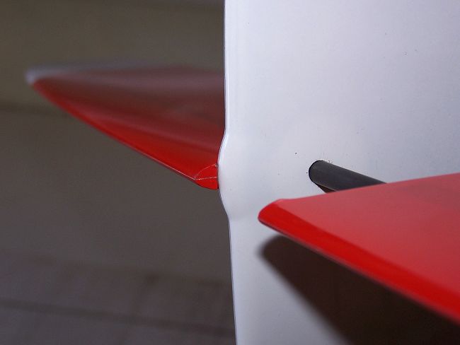
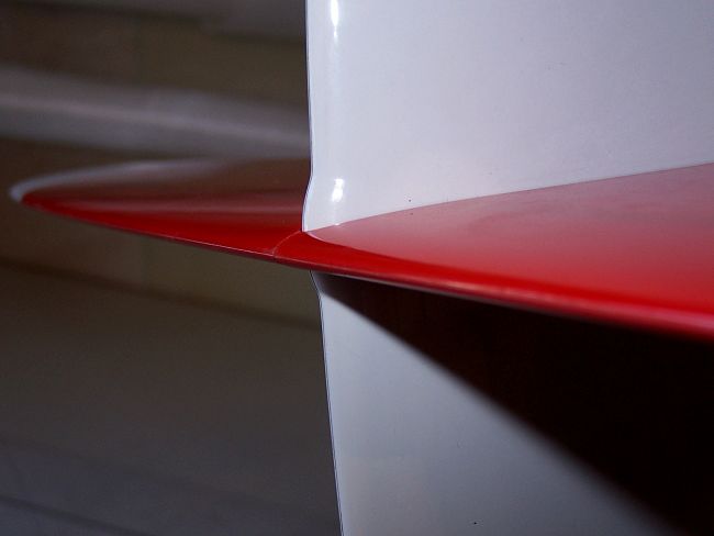
Tail and fuselage:
The cruciform tail has become a standard in F3J, although it has more surface
drag and usually a little more weight than using a V-tail. These disadvantages
quickly disappear when a proper sized cruciform tail yields a powerful rudder,
which is handy for tight and accurate circling. Besides, an all-moving elevator
will make dealing with the angle of incidence very easy. All in all, the
cruciform tail seems to be the best choice of tail configuration because of its
easy handling.
Nevertheless, the size, aspect ratio, tail arm, and section of the tail need to
be considered as important factors for the stabilization of the plane. The
higher the aspect ratio of the rudder and elevator, the steeper the Cl/a-curve
will be. With increased aspect ratio, the stabilization factor will increase.
Again, to avoid too high airfoil drag on the rudder and elevator, the aspect
ratio should not approach extreme values. Using modern airfoils, which will
still work fine at Reynolds numbers below 40k, aspect ratios of 7.5 for the
elevator and 3 for the rudder are achievable. The HT-airfoils designed by Dr.
Drela have shown to be relatively dragless at low Reynolds numbers with no
dead-band around the zero-lift angle. Both, elevator and rudder of the Pike
Perfect are sectioned with a transition from HT-14 at the root to HT-13 at the
tip. To avoid additional drag at the tail, the elevator is assembled very
tightly to the rudder, with its leading edge being joined and taped together in
front of the rudders leading edge. With this type of assembly, the gap between
the elevator parts and the rudder is kept minimal, and no triangular cutouts in
the trailing edge of the elevator are necessary to enable the full deflection of
the rudder. To provide enough elevator control, especially with fully set crow
brake in the landing approach, the elevator area chosen is a little larger than
theoretically necessary.
For precise landings, a down swept nose of the fuselage will help to slow down
the model, immediately after the touch down. The nose kink of the Pike Perfect
is 5° relative to the root chord centerline. The nose is reinforced with
additional carbon layers and has only a small canopy, which does not weaken the
fuselage structure, so hitting the landing target doesn’t damage the model. The
fuselage surface is kept very smooth to avoid additional drag. A very thin tail
boom diameter is hard to construct when stiffness and light weight are
paramount, so concessions in favour of a light fuselage were made by enlarging
the diameter to a reasonable proportion of strength and surface. Finally these
dimensions of the fuselage provide a better grip to control the plane under
great line tension before the start of working time.
Philip Kolb 2005/2006
English rewriting: Larry Jolly

Copyright Samba model 2006