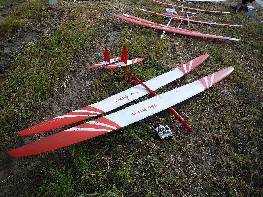
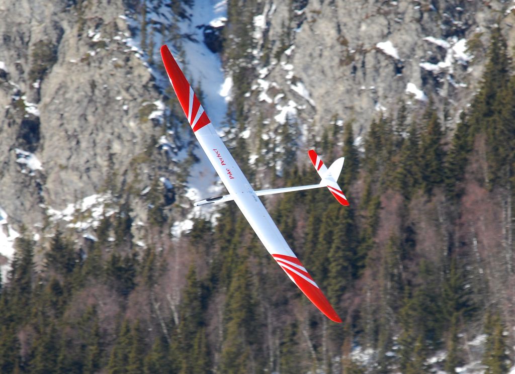
Pike Perfect ET (Extended tips)
To make something which you call „perfect“ even better seems to be a very hard task. But for the season of 2009 we wanted to offer an add-on to our successful Pike perfect. It didn´t need ExtraTerrestrial help but some time here on earth to calculate about the pros and cons for an “Extended Tip”-Version of our Pike perfect. Finally with the beginning of the 2009 flying season we are able to offer the Pike perfect ET to our customers.

Here are some lines from the designer Philip Kolb about the new wing tips and their development:

There is a kind of idiom heard very often in soaring: “Bigger is better!”
This simple sentence implicates that larger planes are able to offer more performance. It is true that far, that purely wingspan has the most effects on a sailplanes´ performance. Speaking about the performance of a sailplane means speaking about its lift to drag ratio (L/D) and secondarily about its endurance capabilities (L3/2/D). A higher L/D offers the pilot more ground to cover in the same time as a higher L3/2/D offers longer hang-time. Both are very important in F3J competitions especially in what is called “weak conditions” (low lift, less to no thermal activity).
The typical lift coefficients an F3J-glider flies at are mostly in the range between Cl = 0.6 to Cl = 1.0. In this lift range the proportion of the induced drag to the overall drag of the aircraft is paramount. Induced drag is affected mostly by wingspan (aspect ratio and planform as well), therefore it is obvious that an enlargement in span is the most efficient way to achieve gains in L/D.
While designing the Pike perfect emphasis was not only put on plain performance parameters. An all around F3J model like the Pike perfect should as well offer agility and easy handling so besides performance aeromechanical, structural and practical (economical) parameters were weighted in importance.
Considering this, the most important question coming up was:
“How much of extension is possible without significant structural, aeromechanical and thereby handling drawbacks?”
Since the centre panel planform is preset the freedom of enlarging the tips is not endless due to the given outline of the centre panel. Designing a complete new wing (or better said airplane) might surely be the more optimal consequence, however it is way more economic to extend the tips and not the whole wing as everybody can imagine.
The driving factors for the planform layout were sweep and taper ratio. One has to be very careful not to run into too narrow tips on the one hand side and not too much back sweep on the other.
Excessively narrow tips can lead into unwanted stall characteristics for the tips tend to stall first (higher local lift coefficients!) and higher drag due to lower Reynolds numbers at lower chords. Huge amounts of back sweep have a negative effect on the coupling of torsion and bending loads. This needs to be compensated with a stronger and thereby heavier build up.
The resulting planform of the Pike perfect E.T. in comparison to the original Pike perfect planform is shown in Fig.01.
To contribute the planform with its slightly lower Reynolds numbers on the tip a new tip section was designed. The target was to shift the laminar drag bucket upward so that a higher Clmax is reachable. This action needed to prevent tip stall the more attention was turned on the performance of the airfoil in the range of L/D max and maximum endurance in the given Re-number regime.


Comparison of tip-airfoils

The non linear airfoil transition from the tip’s root chord (airfoil PK-91B) to the tip (airfoil PK-995) was designed and developed according to the method described in the Pike perfect development article. For this new transition the airfoils were designed for their local Re*sqrtCl range to offer more equal Clmax values along the span and less drag in the higher lift range from Cl = 0.5 upward.
First calculations show a reduction in sink rate of about 3% with the extended tips compared to the original ones operating at the same wing loading. This reflects in about 20sec. more dead air time out of a 200m launch. Of course flight tests and measurements need to be done to validate these numbers as well as to check out if the drawbacks of the new wingtips which are reflected in less roll rate, less maximal possible bending loads when using the same spar layup and less yaw damping are as minimal as estimated.

March 2009, Philip Kolb


Modelpolar-Comparison between Pike perfect and Pike perfect E.T.
at the same wingloading with 0° flap


Modelpolar-Comparison between Pike perfect and Pike perfect E.T.
at the same wingloading with 2° flap


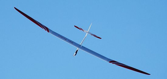
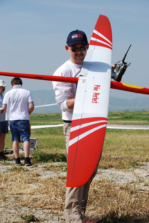
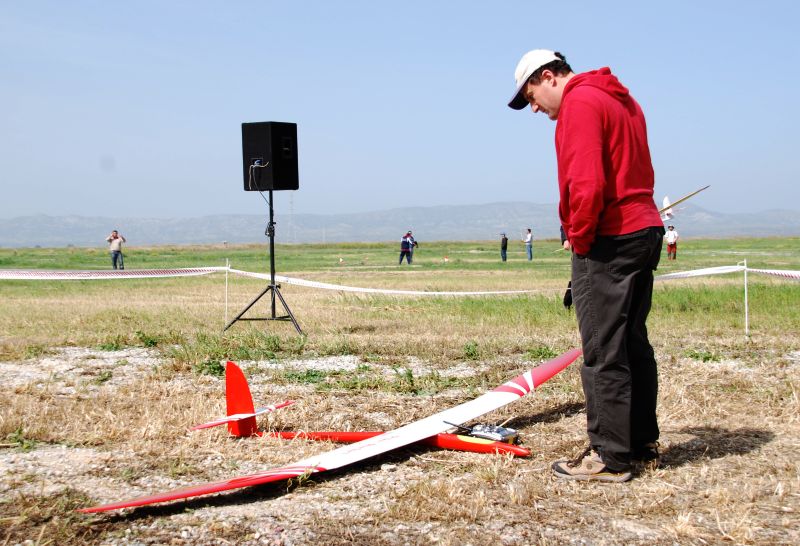
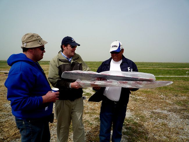
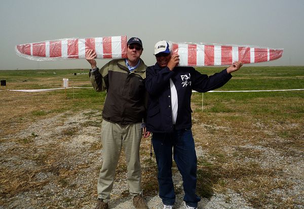
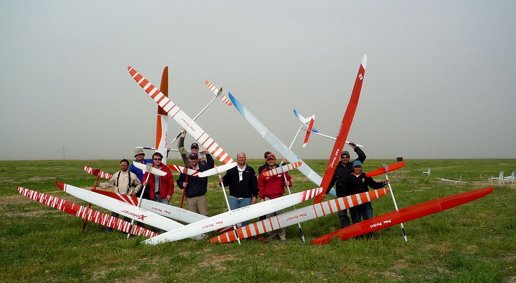
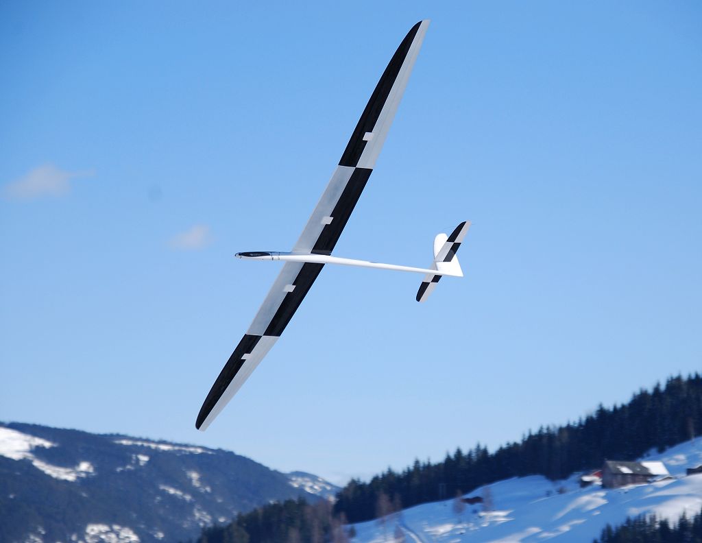
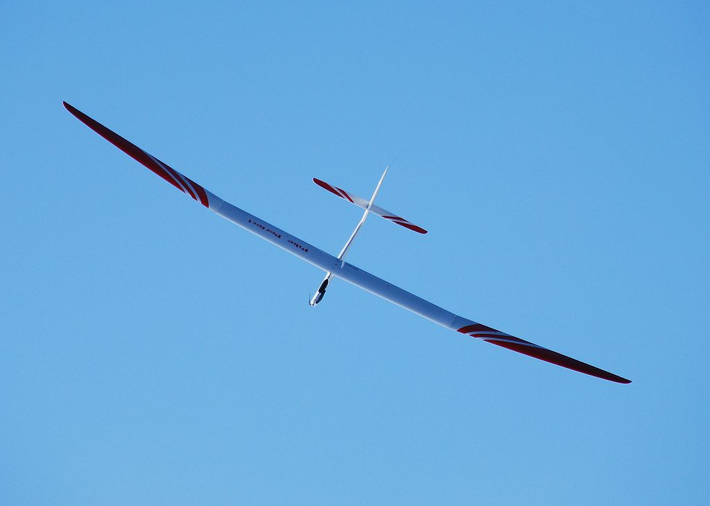
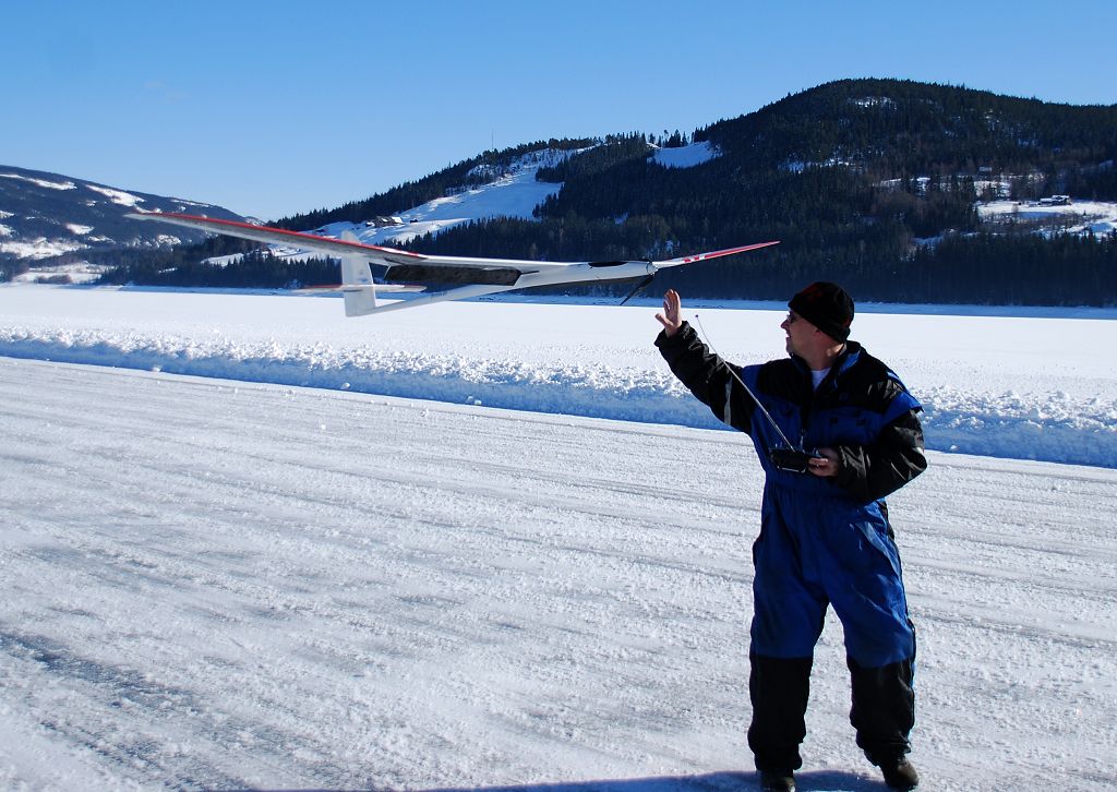
Some pictures from first flights in Cyprus 6-8.march:


Read Jojo's diary writeup from this event HERE


Some pictures from first electric flights in Norway 11.march:


Copyright Samba model 2009