 |
 |
 |
 |
|
|
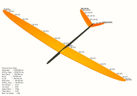
It has been 5 years since we released the Pike perfect, one of the first real ‘standard F3J-planes’. In cooperation with Philip Kolb we managed to push the frontiers in F3J plane design. Five years later we are happy to publish another great soaring machine out of our ‘Pike-series’. This time we were able to acquire the help of Johannes Dillinger, Philip Kolb and Benjamin Rodax to add their experience and expertise in designing, calculating and computing to the creation of the Pike precision, our new F3F / F3B competition sailplane. Here is an insight into the design of our new F3F / F3B model airplane by the design-trio.
Tooling of moulds was made on HSC tooling machine Röders RFM 600/2.to reach the
top quality. Machine is working with accuracy of 0,002 mm. Construction job was
made in system Pro/ENGINEER Wildfire 4.0. Model is produced with newest known
technologies and with usage of newest high tech materials. Model will be
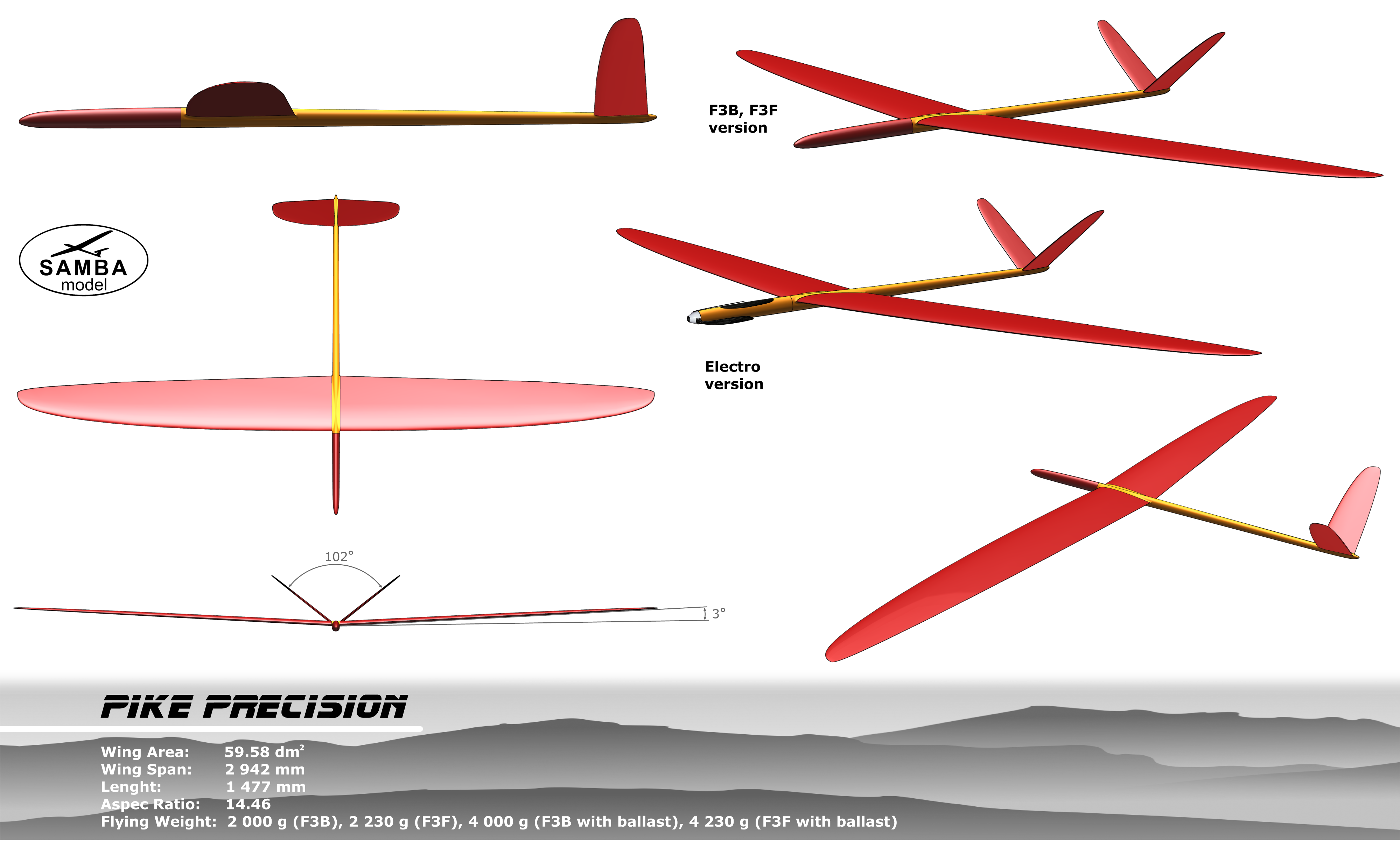
produced in 2 basic versions + other versions on customers requests. Basic
version is F3B with weight up to 2000 g, second version is F3F with flying
weight about 2200g and will be more solid for harder manipulation on the slope.
Maximum ballast is 2kg and CG (center of gravity) will remain the same.
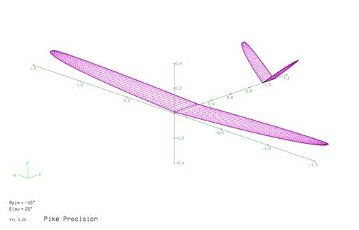
Send us your own design by downloading the 3d-view HERE
More pictures
from the first models -
video of
first flight ever -
copy Update:
NEW LDS for Precision
NEW slim fuse Precision
Very successful Eurotour F3F total
- The Pike Perfection is now available with servo covers and
Easter F3F Hansholm, Denmark 2012 Second day of flying and first competition. Radovan Plch ended 4th at F3F Eurotour in Donovaly 24-26.6.2011. After some radio problems in the first rounds he started to climb and finished just after the 3 Austrians on the podium. Excellent pictures HERE
Over the last five years we able to accumulate lots of knowledge and information on sailplane design due to several projects we have been working on. The Pike perfect was the initial kick-off point towards that. Many model airplane pilots and builders have asked for help on their specific projects, which sometimes successfully came to life but at other times were sadly only taking lots of our effort and time and were not successful to our satisfaction. To justify all the work we had put into the various designs, we decided to go for our own F3F / F3B design without any trade offs using the latest of our design and development capabilities. Designing the plane to be produced by Samba-model, our partner and producer, who we considered capable of achieving all the optimization results in the best possible way, just reflects the logical conclusion. To accomplish superior solutions we chose a multidisciplinary, iterative design process to search for the ideal compromise between aerodynamic/structural performance combined with easy flying characteristics to achieve the optimum performance for competitions. Prior to starting with the actual design we wanted to analyze the flight envelope and the typical lift coefficients flown in the most important segments of the F3F and F3B flight tasks. Our experience with inflight measurements and data collected from F3J flight-testing set a base to work from for this specific analysis. On the one hand it is important to check and calibrate the analysis tools and on the other hand to define the flight segments for F3F and F3B tasks in a variety of weather conditions. Therefore inflight tests were performed during one summer in all F3B and F3F training flights with an Ascot F3B model and the Eagle Tree System on board. Measuring altitude, airspeed and acceleration in lift and drag direction the aircraft's lift coefficients were evaluated with the aircraft's mass. The statistical distribution of lift coefficients helped to define the requirements for the aerodynamic design. Furthermore the acceleration measurements were used to identify typical load cases needed in the structural design process. After collecting and analyzing the flight data we tried to separate the topics to work on into three basic fields:
Although these subdivisions interact strongly with each other it proved to be very helpful in organizing the development and design process of Pike precision, separating the design work into specific topics. This way we could use our abilities and skills in the most efficient way to finally study and understand these interactions, finding the best compromises for the final solution.
Aerodynamic design of Pike precision
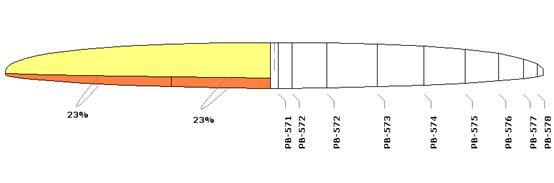
The wing sweep was designed to achieve a constant chord for the flaps and ailerons of 23% of the local chord depths. This also helps to reduce induced drag by keeping the design load distribution (no steps, bumps or kinks) while cambering or reflexing the trailing edge surfaces. For the two-piece V-tail we adopted the same considerations while designing the planform. the only exception is the chord width of the control surfaces which are slightly wider at 30% constant chord.
One of the most
critical questions in the design process is the development of adequate airfoils
and their optimization. With today's available design tools, it seems that you
have endless possibilities to tweak. Therefore one can very easily get caught
out somewhere in the design loop trying hard to improve the ‘’off design’’ areas
and not stepping ahead ‘’on design’’. Data collected from the various flight
tests was a huge asset in gaining reliability for our calculations as well as
validation of the results.
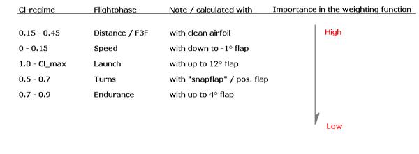
By utilizing this weighting function we could balance trade-offs and performance gains in a very elegant way, saving one or the other dragcount in important areas while not giving up too much in less important areas of the flight envelope, or at least only in the designated ‘’off design’’ areas.
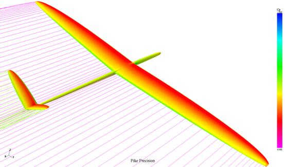
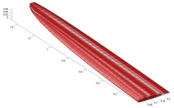
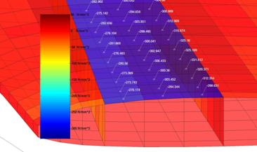
Fig. 4 Aerodynamic analysis of full configuration with 3D panel code' Equally important as developing a high
performance main airfoil was the design of the tip airfoil and the airfoil
transition along the span. Especially in the case of the Pike precision with its
high taper ratio and thereby rather narrow tips the local airfoils needed to be
designed to work flawlessly at lower local Reynolds numbers. To enable the
handling advantage of the high taper ratio wing, we paid highest attention to
boost the more than ‘’sufficient’’ Cl_max performance of the tip airfoil. Using
washout in the wing tips to prevent tip stalls was not considered because of its
negative effects on the planes’ high-speed performance. Therefore the tip
airfoil was designed to reach comparatively high Cl_max values. Secondly the tip
airfoils should at least come up with performance characteristics as close as
possible to the main airfoils’ characteristics, adapted of course to the local
Reynolds numbers. Finally we paid special attention to the geometric shape of
the tip airfoil and its local thickness around the hingeline where subspars are
located. As the ailerons run all the way out to the tip, subspar height is
critical since it strongly affects the torsional stiffness of the ailerons.
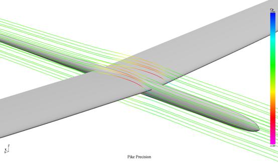
Fig. 5 Streamline flow visualization of wing-fuselage junction General arrangement & flight mechanics of Pike
precision
Structural investigations and calculations were
performed to optimize structural mass and realize the aerodynamic potential of
the aircraft. These relatively new methods and possibilities are called
aeroelastic tailoring and display completely new possibilities in aircraft
design. To our knowledge these steps were not taken in model airplane design
before. We were very happy to fall back on the knowledge and virtuosity of
Johannes Dillinger, one of the designers on the new Open Class Sailplane
‘’Concordia’’ of Dick Butler.
The goal in structural design is therefore twofold. The structure is designed to cope with all loadings without failure by virtue of surpassing exceeding maximum allowable strains/stresses in every single layer (Fig. 9, stress in spar layer).
As
already mentioned, the second fundamental task is to maintain the aerodynamic
shape. This not only relates to the airfoil shape (of course), but equally
important to the zero-wing-twist distribution, being essential for minimum
induced drag. Especially in high-G turn maneuvers and during the launch phase
with temporary high lift-coefficients, it is enormously important for superior
aircraft performance to maintain an optimal lift distribution, preserving the lowest possible induced drag and therefore the high
flight velocity. For both flight conditions, the aircraft's normal acceleration
is a multiple of the usual 1g steady flight condition, meaning that the lift
will have to be a multiple of the aircraft's weight. Aeroelastic tailoring aims
at retaining a nearly untwisted wing throughout the entire range of important
load cases.
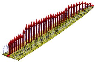
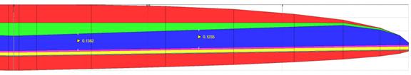
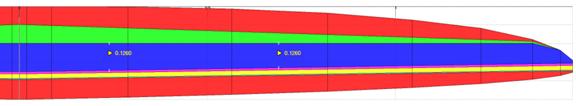
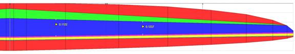
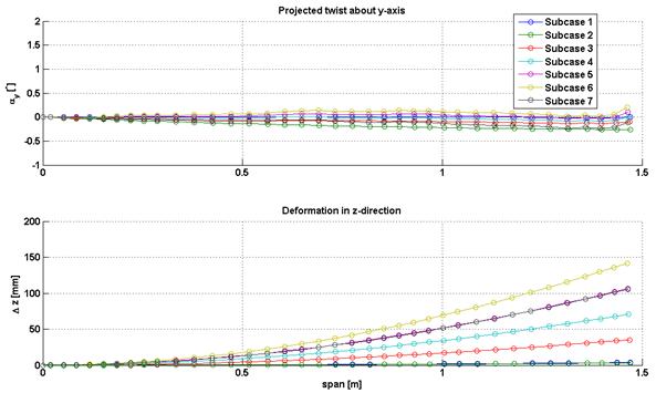
Fig.10 Sample of investigated spar positions
Fig.11 Optimized twist distributions and wing bending for most relevant load cases Philip Kolb, Benjamin Rodax and Johannes Dillinger
|